TECHNICAL REFERENCE

Introduction to BLAC INC. FCC Slide Valve ESD Functions
Backstory – When BLAC INC. was founded in 1990, our goal was to build electro-hydraulic actuators. The emphasis was to manufacture FCC slide valve and butterfly valve actuators that were the best in the industry with the highest reliability and best-in-class maintainability. We believe that we have achieved these goals.
When FCC refiners and licensors began specifying dedicated emergency shutdown (ESD) functions for valves, BLAC INC. responded by designing the most reliable system in the industry. The UOP Electrohydraulic Actuators specification has been considered the industry baseline to follow since 1979.
In the mid-1990s, UOP specified the use of two (2) ESD solenoid valves, wired in series (2 out of 2), so that a failure of one solenoid valve would not cause a nuisance shutdown of the FCC unit. At that time, the refining industry was more worried about unintended shutdowns of the FCC unit rather than failures to trip due to a solenoid not working properly.
After all, until the late 1990s most FCC units in the world did not have an automated shutdown system. Some refiners even used a single “energize to trip” ESD solenoid to avoid nuisance shutdowns.
Except for the 2oo2 solenoid configuration, UOP did not specify how the rest of the hydraulic system was to be configured. This was left up to each vendor.
Unlike other vendors though, BLAC INC. selected to incorporate redundant ESD hydraulic valves in the ESD circuit which provided enhanced ESD system availability.
For the purpose of technical evaluation and comparison – BLAC INC. is providing the technical information behind 2oo2 Voting, 2oo3 Voting and Safety Integrity Level (SIL). We believe it is important to review the operation of this functionality since safety and ultimate reliability are primary concerns.
It is not sufficient to simply use three (3) ESD solenoid valves with no ‘logic’, no diagnostic monitoring, simplex hydraulic valves, no accumulator precharge measurement, or no continuously operating fluid cleaning systems.
We therefore believe that the design we are offering is far superior to other electro-hydraulic actuator emergency shutdown functions available in the marketplace.
For more information on the 2oo2 and 2oo3 ESD manifolds, components and integration with the servo control manifold, see here.
Otherwise, the technical information on ESD voting and SIL follows below.
2oo2 Voting Emergency Shutdown Function
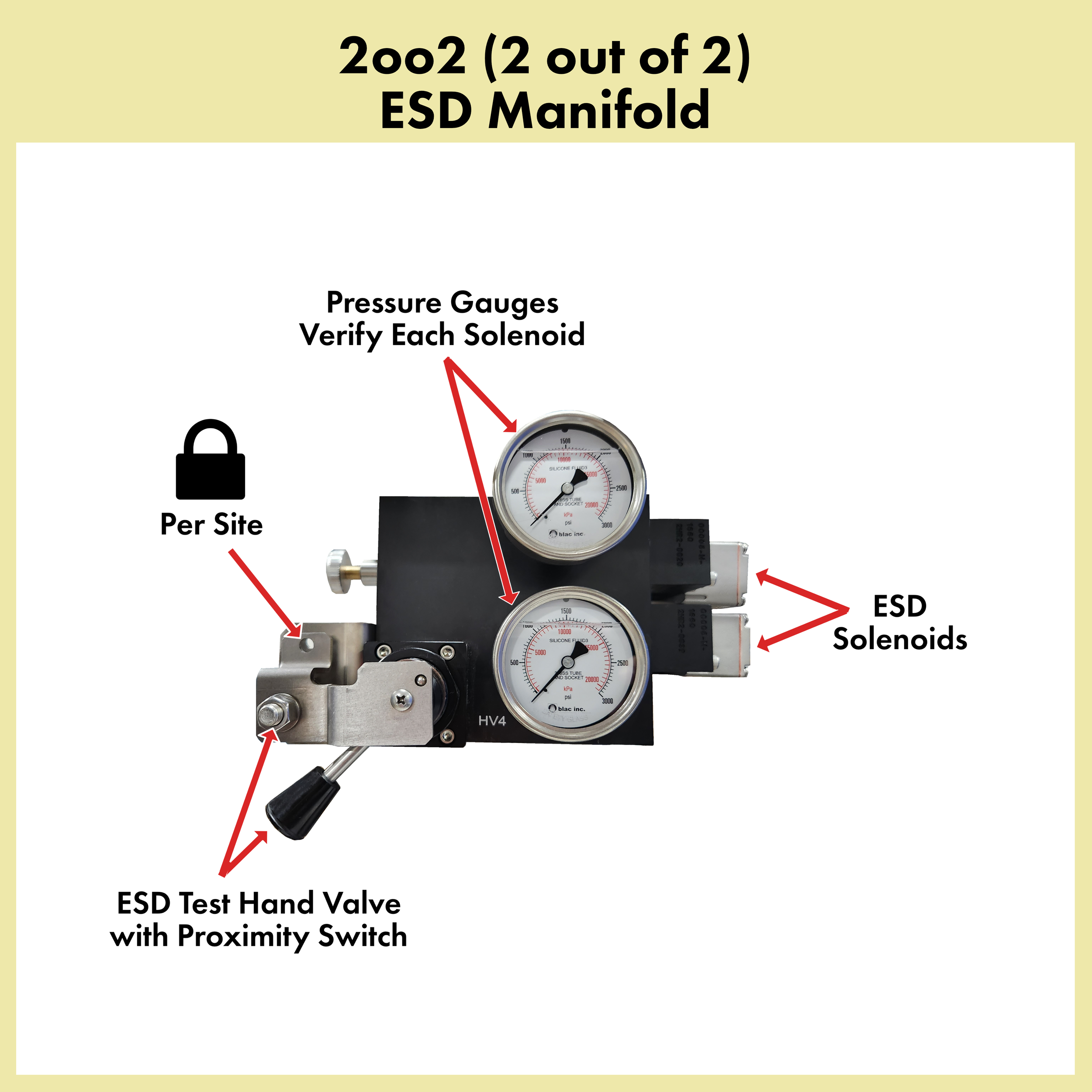
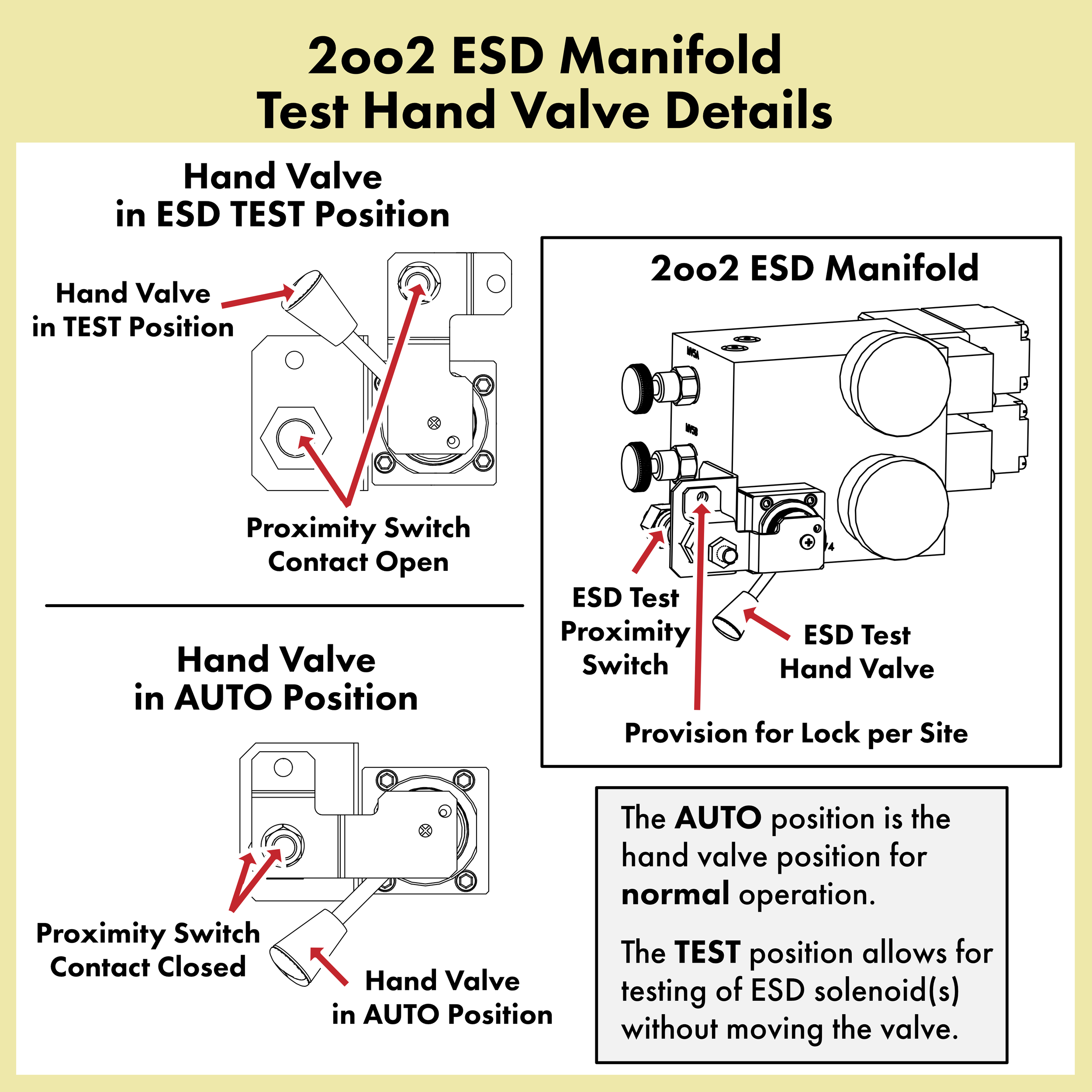
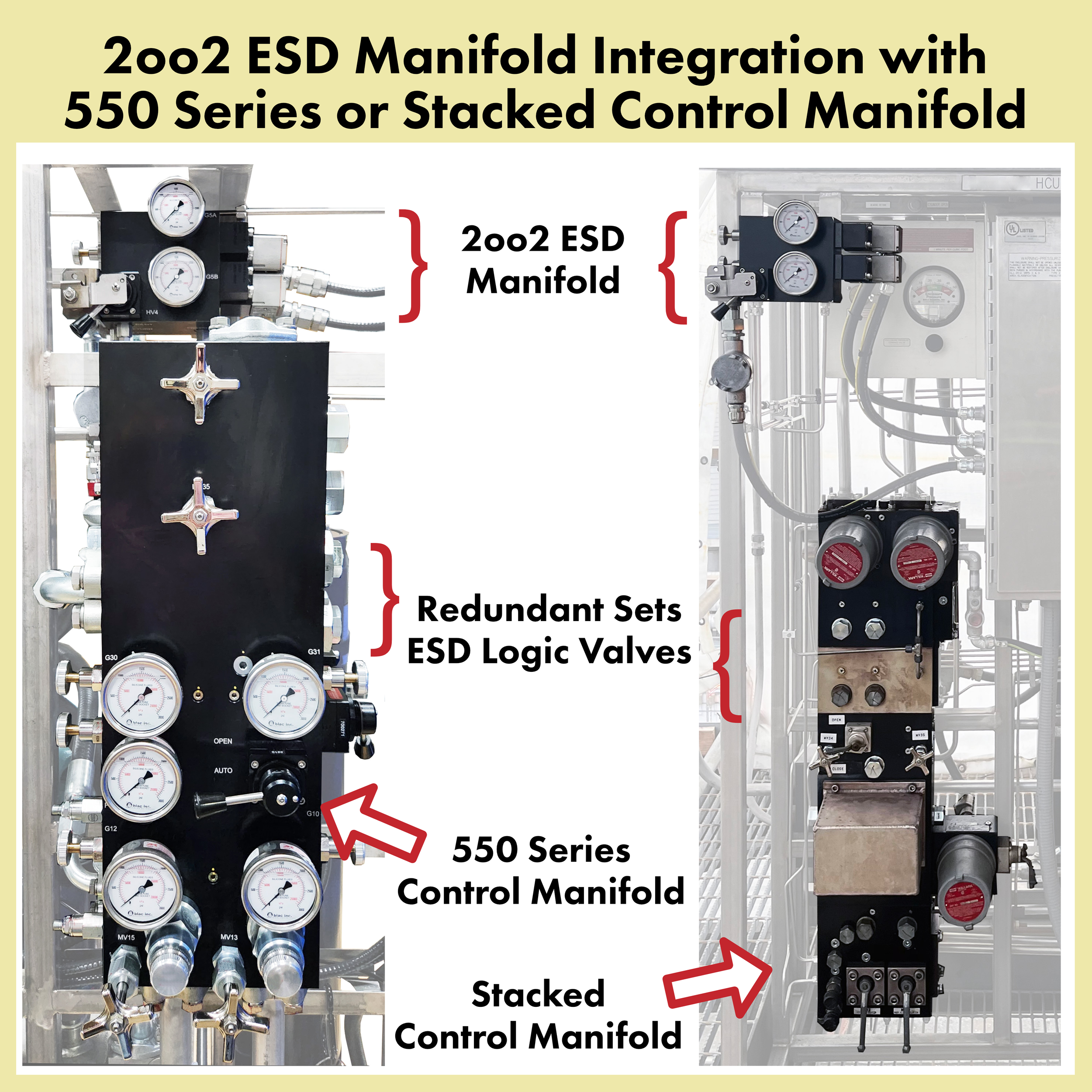
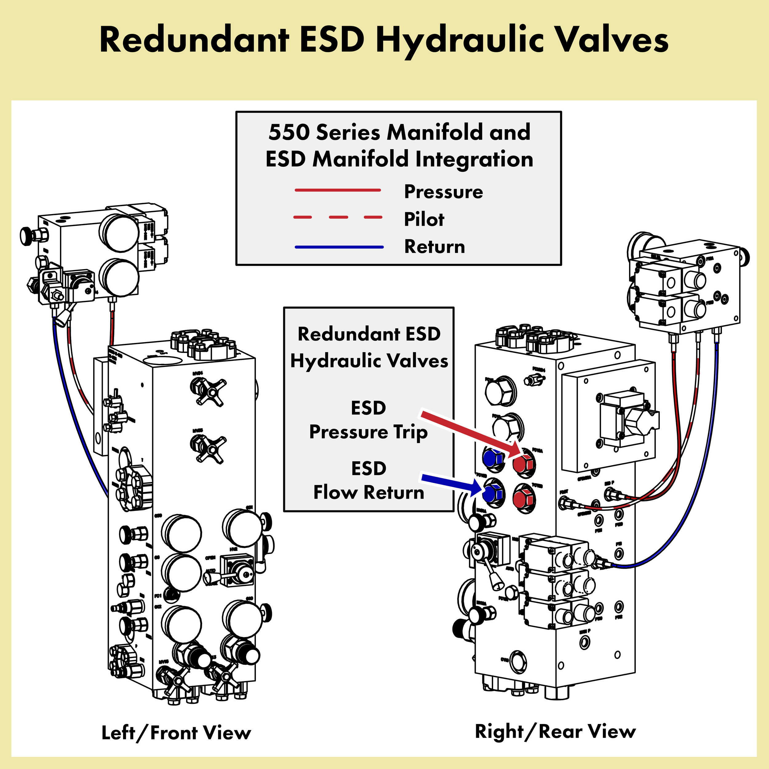







For 2oo2 voting, the two (2) ESD solenoids are powered by the refinery SIS. When both ESD solenoids are de-energized, hydraulic pressure opens the ESD hydraulic valves, causing full pressure and flow to one side of the cylinder, and releasing pressure to tank on the other side of the cylinder. This moves the valve as fast as possible to the ESD position (generally 2 seconds for slide valves, down to 0.3 seconds for butterfly valves).
The signals to the ESD solenoids are monitored by relays, wired in parallel to the ESD signals. When both ESD solenoids are de-energized, the Lock-in-Place solenoid also de-energizes, isolating the servo valve. This avoids the position control servo valve from fighting the ESD function. However, while this extra step is an extra safety measure, the ESD function is inherently able to override the modulating servo control.
The “ESD Test” switch can be used to regularly check that the ESD function works without causing the valve to move. When the switch handle is moved out of “Normal” mode, an alarm is generated to alert the operations staff that the ESD function has been bypassed for testing. In the “Test” position, the solenoids can be safely de-energized for the test.
This 2oo2 ESD function system can be added or retrofitted to virtually any hydraulic system that needs to have a failsafe function. We have performed this modification on several systems worldwide and on the equipment from multiple hydraulic system manufacturers.
For a closer look at the 2oo2 ESD manifold components and integration with the servo control manifold, see here.
2oo3 Voting Emergency Shutdown Function
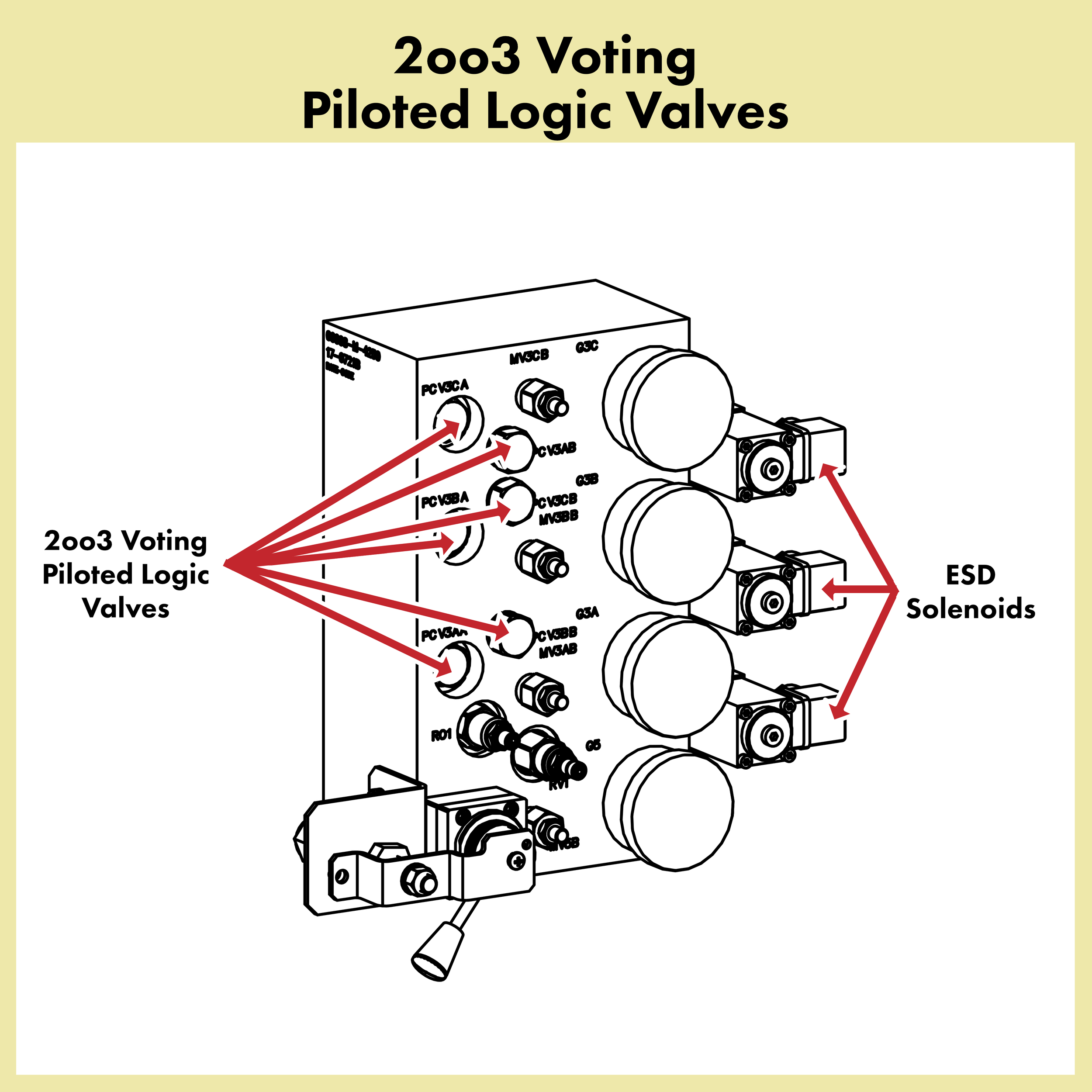
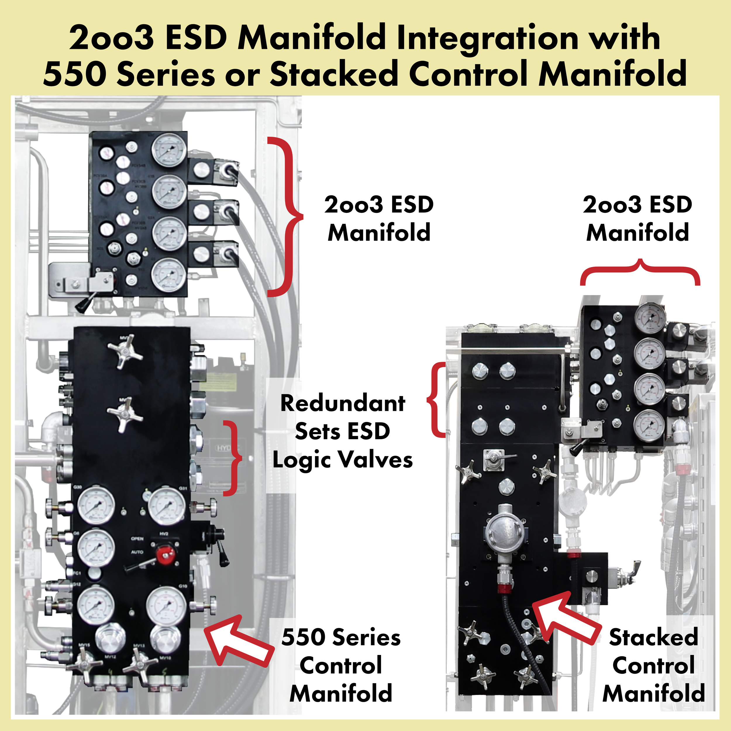
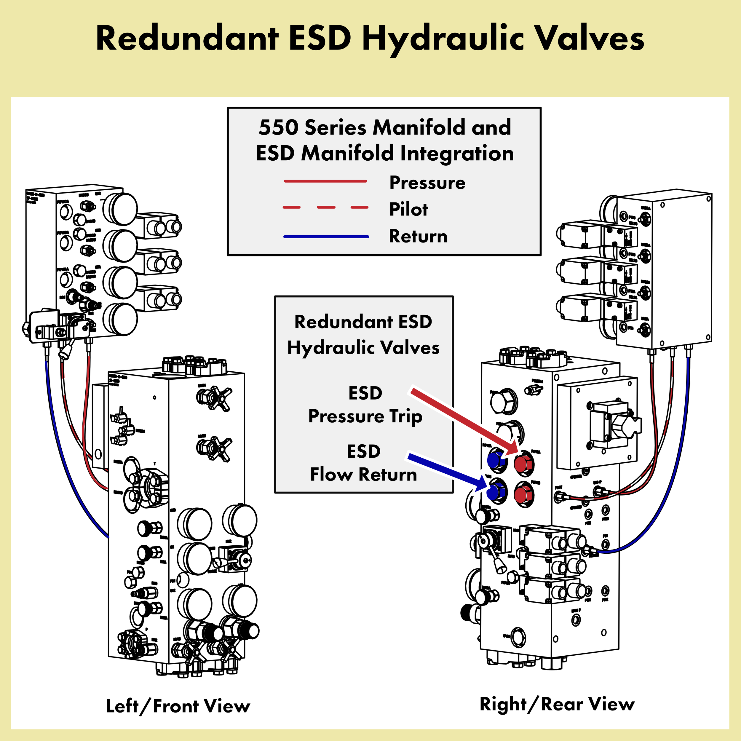







The 2oo2 ESD function was the standard offering until 2016 when BLAC INC. developed a 2 out of 3 voting ESD solenoid system.
While the 2oo2 solenoid ESD function has been very successful for 30 years, demand for more reliability and availability has led to the use of 2 out of 3 voting for many facets of refinery SIS systems.
BLAC INC. developed the 2oo3 voting ESD system to be used both in new systems as well as a retrofit replacement for older 2oo2 systems.
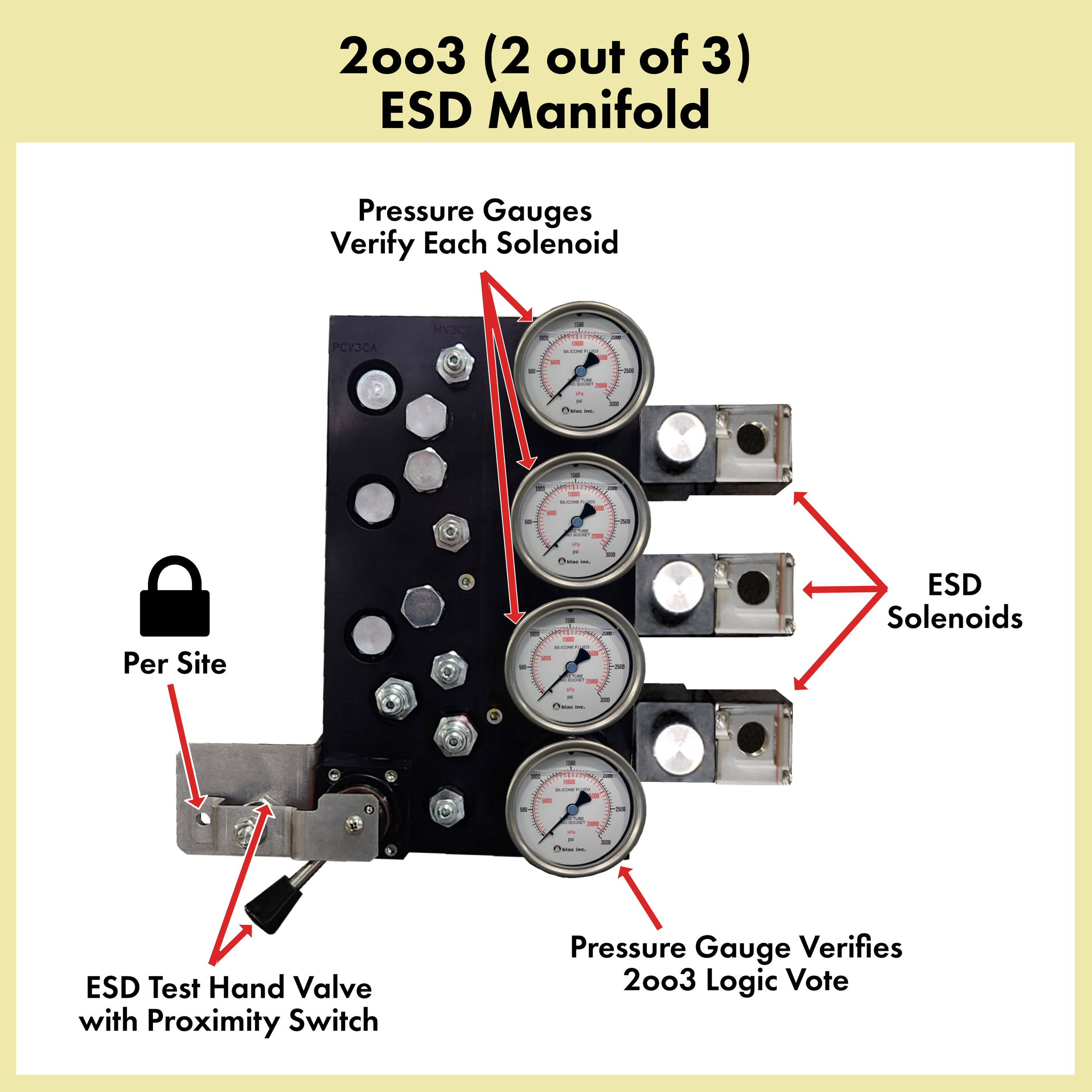
The three (3) ESD solenoids are powered by the refinery SIS. When the solenoids are energized, hydraulic pressure holds the ESD hydraulic valves in the closed position, permitting normal modulating operation of the slide valve.
When any 2 out of 3 (2oo3) solenoids are de-energized, hydraulic pressure is removed from the ESD hydraulic valves, causing full pressure and flow to one side of the cylinder and releasing pressure to tank on the other side of the cylinder.
This moves the valve as fast as possible to the ESD position (generally 2 seconds for slide valves or down to 0.3 seconds for butterfly valves in expander turbine systems, depending on application and specifications).
The signals to the ESD solenoids are monitored by relays, wired in parallel to the ESD signals. When 2oo3 ESD solenoids are de-energized, the Lock-in-Place solenoid will de-energize, isolating the servo valve. This avoids the position control servo valve from fighting the ESD function.
Each solenoid valve is monitored by a pressure gauge and a pressure transmitter. When an individual solenoid is de-energized, its corresponding pressure gauge and transmitter will show the pressure draining from operating pressure to zero.
A fourth pressure gauge and transmitter are used to monitor the result of the 2oo3 vote. This pressure gauge will show zero (0) pressure when the system is tripped by multiple ESD solenoids being de-energized.
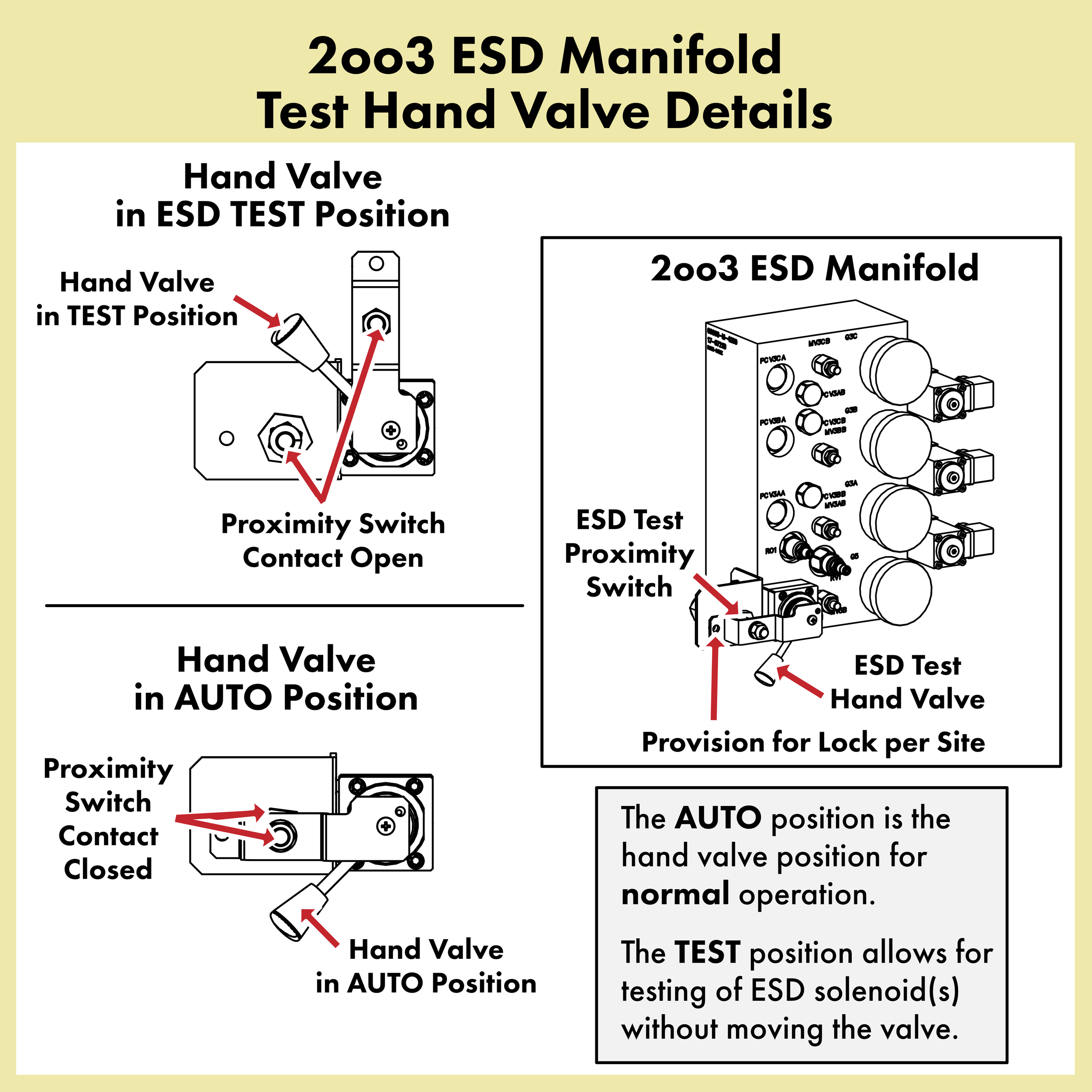
The “ESD Test” switch can be used to regularly check that the ESD function works, without causing the valve to move. When the switch handle is moved out of “Normal” mode, an alarm is generated to alert the operations staff that the ESD function has been bypassed for testing. In the “Test” position, all solenoids can be safely de-energized simultaneously for the test.
However, if desired, each solenoid can be de-energized one at a time without bypassing or placing the “ESD Test” switch in “Test” position.
Again, this 2oo3 ESD system can be added on to other hydraulic manufacturers systems to provide emergency trip functions.
For a closer look at the 2oo3 ESD manifold components and integration with the servo control manifold, see here.
Safety Integrity Level (SIL)
More and more refiners are requesting that FCC actuator vendors supply “SIL Rated” systems.
The relevant standards (ANSI/ISA S84.01 and IEC 61511) apply a SIL to a “Safety Instrumented Function”. The Safety Instrumented Function is not simply the ESD solenoids, but the entire hydraulic system (and indeed, the entire SIF loop from process measurement to logic solver to final control element) that performs the ESD function.
This includes the reservoir, pumps/motors, accumulators, nitrogen precharge, tubing, hydraulic valves, solenoids, hoses and cylinder. It also includes the diagnostic coverage of the instrumentation as well as online redundancies and backup systems.
To determine the SIL of the “Safety Instrumented Function”, the probability of failure on demand (PFD) of each component should be evaluated, and the system as a whole analyzed. BLAC INC. hired Kenexis Consulting to provide a 3rd party analysis (using the Fault Tree Analysis method) of the entire system function to determine the PFD and SIL of the ESD functions as well as the nuisance trip rate.
The calculated SIL for the ESD actuator function is listed in the following table:
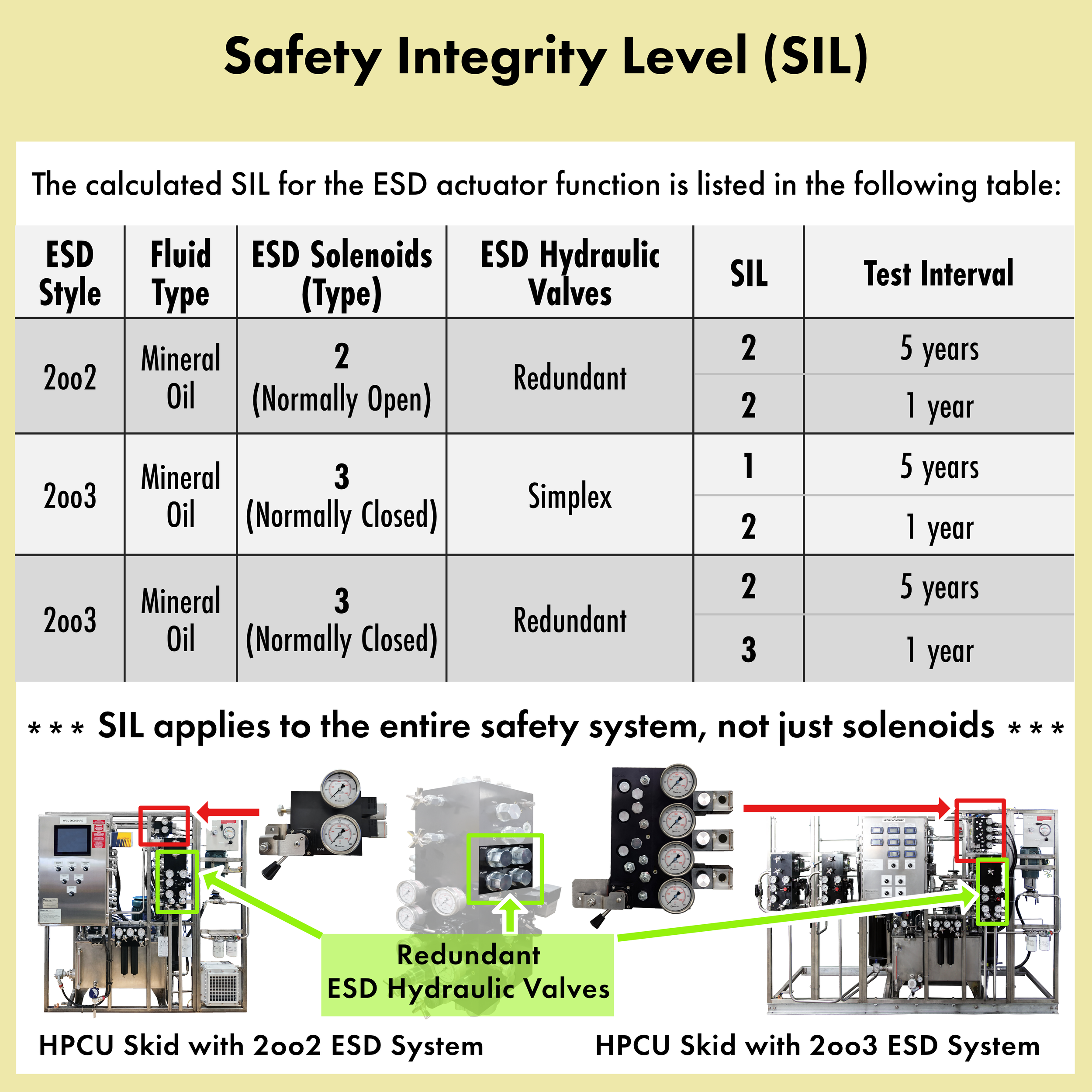
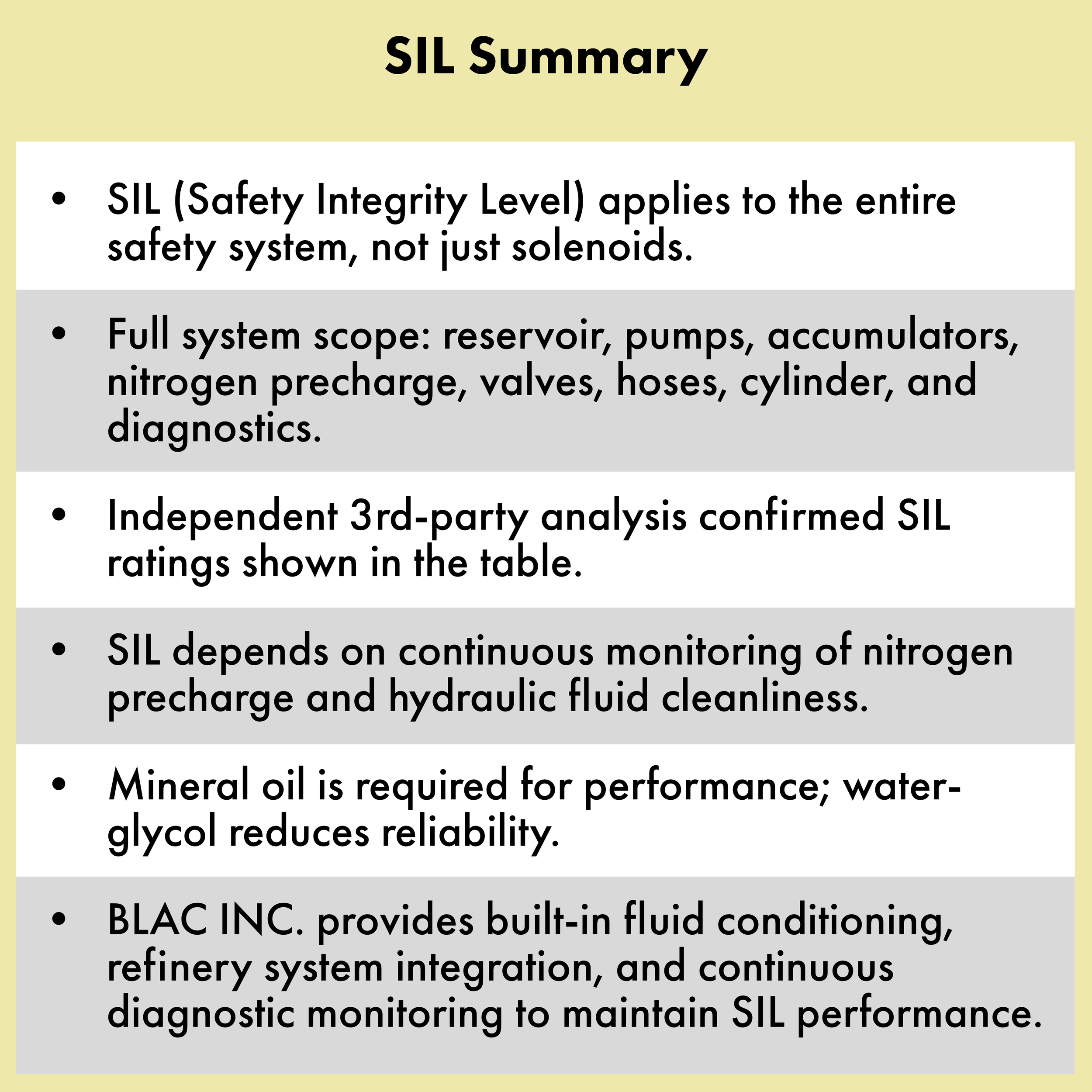



The above SIL ratings are based upon inclusion of specific features and system diagnostics. The nitrogen precharge of the Emergency Accumulators must be always monitored to maintain any SIL rating.
Further, the fluid cleanliness is a major factor in achieving SIL rated systems. If the fluid is not cleaned properly and continuously, then the fluid performance degradation will result in a higher failure probability, reducing the SIL.
Therefore, BLAC INC. provides a hydraulic fluid water and particulate removal system that functions continuously with information that may be monitored for display on refinery BPCS/DCS screens and on the local HMI at the skid or remote PLC enclosure as applicable. In addition, the fluid type basis is mineral oil. Water-glycol fluids have degraded performance versus mineral oil and should not be used.
All diagnostic monitoring is continuously recorded by the BLAC INC. Intelligent Monitoring Controls and will always confirm performance during operation.
Improper Stuffing Box Purge
Purge media to a slide valve bearing sleeve is required to keep particles and process gas from entering the slide valve packing. A loss of purge flow may cause the slide valve to stick, coke to form around the stem, or packing failure, leading to a loss of containment of the process.
Too high a purge flow, and the valve stem, disc or orifice plate may erode prematurely, causing a unit shutdown. This relatively small flow rate must be controlled within a narrow range to be most effective.
BLAC INC. provides different solutions to this problem. System offerings like intelligent purge or automated purge control are direct replacements for the older panels that are restriction orifice based purge systems.
However, the basic purge panel style is still a very effective method and with BLAC INC. designing for the actual process conditions, the proper target purge flow can be established. The restriction orifices are sized to limit the maximum purge velocity.
Contact us for information on the best options for your purge operation needs and see Valve Packing Gland (Stuffing Box) Purge Control Panels for information on our solutions.
Goggle Valve Cylinder Replacement
Goggle Valve Cylinders Replacement for Z&J Supplied Goggle Valves
BLAC INC. manufactures a cylinder to replace the OEM Cylinders built for Z&J Goggle Valves.
The cylinders we manufacture have several key improvements to the design to prevent problems that occur with the Z&J cylinders:
Body of cylinder is constructed from High Strength Aluminum instead of the steel OEM cylinders.
Repair of the cylinder can be done in place. Existing OEM cylinders must be removed and taken to a shop to be refurbished.
Improved seal design over the extremely poor seal design in OEM cylinders that leak within months in most cases.
Cylinder bore is improved in size to provide more force to unclamp.
Rear cylinder rod is provided for manual operation and has a seal to protect from leakage. OEM cylinder does not have a seal.
Limit switch mounting is much improved to gain reliability for limit switch action.
Air is purged through the spring assembly.
Continuous circulation of oil is provided to the cylinder through ports with less pressure drop than OEM. The OEM systems sometimes have enough pressure drop that the unclamping process can take place inadvertently instead of upon command.
Seals for the cylinder are guaranteed by BLAC INC. for 5 years operation with no leakage. This technology has been proven in hundreds of applications.

OEM Installed Cylinder for Goggle Valve
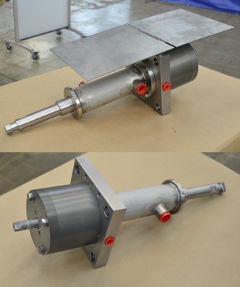
BLAC INC. Goggle Valve Cylinders
